This topic is specific to welding geometry, base material strengths, weld strengths and all other welding considerations.
The weld geometry for each connection is locked by the program. In order to make the connection property inputs easier these geometries may not be altered. The geometries used are industry standard, and illustrated by the AISC.
The weld to support is illustrated in Figure 10-4c of the AISC 14th Edition Manual.
The weld to beam is illustrated in Figure 10-4b of the AISC 14th Edition Manual.
When axial tension is present in the beam, the weld configuration of a single vertical weld on each clip angle (at the support) is inadequate, as that weld would have to resist the tension via torsion in the weld throat. Because no adequate methodology for the torsional strength of weld exists, the program will automatically place a weld on the bottom of the clip angles as well. In addition an Angle Leg Bending limit state is checked to ensure that the unsupported angle leg doesn't fail in bending due to the axial force.
When multiple Double Angle Shear Connections are grouped together (i.e. multiple connections are part of the same Connection Rule from an integrated RISA-3D model), if any connection has an axial tension in its beam for any load combination then all of the Connections in that group will receive the L-shaped weld configuration.
The weld to beam is illustrated in Figure 10-6 of the AISC 14th Edition Manual.
When axial tension is present in the beam, the weld configuration of a single vertical weld on each side of the end-plate is inadequate, as those weld would have to resist the tension via torsion in the weld throat. Because no adequate methodology for the torsional strength of weld exists, the program will automatically place a weld on the bottom of the plate as well.
When multiple End-Plate Shear Connections are grouped together (i.e. multiple connections are part of the same Connection Rule from an integrated RISA-3D model), if any connection has an axial tension in its beam for any load combination then all of the Connections in that group will receive the C-shaped weld configuration.
The weld to support is illustrated in Figure 10-11 of the AISC 14th Edition Manual.
The weld to support is illustrated in Figure 10-13c of the AISC 14th Edition Manual.
The weld to beam is illustrated in Figure 10-13b of the AISC 14th Edition Manual.
Vertical Brace Connections consist of a number of sub-connections:
A fillet weld is placed along the entire perimeter of brace/gusset overlap. If an end-weld is not specified by the user then it is not included. The weld can also be specified as balanced.
The gusset can be directly welded to the beam/column, or clip angles may be used. When clip angles are specified they are given a C-shaped weld at the beam/column in order to accommodate the significant axial forces that such connections typically experience. See the Double Angle Shear Connection topic above for more explanation on this.
The beam to column connection is treated as an ordinary shear connection in the program, with one exception. When Double Clip Angle is specified the clip angles receive a C-shaped weld in order to accommodate the significant axial forces that such connections typically experience.
Due to the uneven force distribution on welds which are placed on the face of HSS members, an effective weld length is used. This makes certain portions of the weld near the center of the HSS member ineffective, and they are therefore ignored. For more information on this see AISC 360-10, Section K4.
Note:
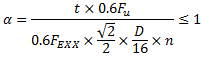
The base material at the location of a weld may have less strength than the weld itself. In this case it will control the overall strength of the welded connection. In order to account for that the program uses a weld strength reduction factor (α). This factor is included in all Weld Strength calculations where the strength of the connecting element is not directly calculable. The AISC Steel Design Manual presents this as a thickness limitation, but RISAConnection has rearranged the equation to the following in order to include it as a reduction factor to the Weld Strength limit state.
D = Fillet weld leg size
Fu = Base material rupture strength
n = Number of welds at base material where there is a weld. n=1 corresponds to AISC Eqn 9-2 and n=2 corresponds to AISC Eqn 9-3. For a connection such as a shear tab, this would be 1 because the number of shear rupture areas of the weld is equal to the number of shear rupture areas of the base material.
t = Base material thickness
FEXX = Electrode strength, including reduction factors specified in notes to Table 8-3 on Page 8-65 of the AISC 14th Edition Manual.
α is used as a strength reduction coefficient for the weld strength. This formula is a rearrangement of equation 9-2 of the AISC 14th Edition Manual.
Note:
The base material proration factor (α) is calculated as shown below:
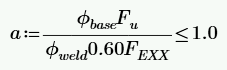
Φbase = Base Material Strength Reduction Factor per AISC 360-10, Table J2.5
Fu = Base Material Tensile Strength
Φweld = Weld Material Strength Reduction Factor per AISC 360-10, Table J2.5
FEXX = Electrode strength
Welds may be analyzed using an elastic force distribution or an Instantaneous Center of Rotation force distribution method. You can control which method is used through the Global Parameters.
Note:
The design of the weld between the angle and the column is complex due to the compression block between the two angles bearing on each other through the beam web. The AISC 14th Edition Manual offers a formula for elastic design of this weld (equation 10-1) which is derived in Blodgett's "Design of Welded Structures" Section 5.4. This formula is used to calculate the weld strength for the double angle to support connection. Out-of-plane eccentricity is ignored.
When axial tension is present in the beam the geometry of the weld is modified as explained in Weld Geometry. Axial compression in the beam is ignored for the weld to the support.
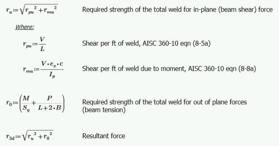
The design of the weld between the angles and the beam uses the procedure detailed on page 8-12 of the AISC 14th Edition Manual. In-Plane eccentricity is taken as the distance between the COG (center of gravity) of the weld group, and the face of the support.
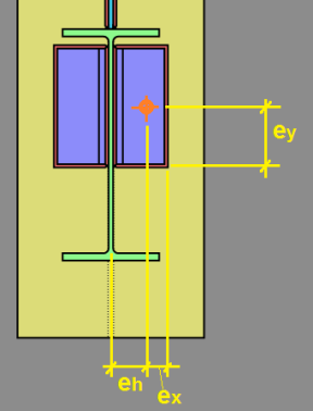
The Polar Moment of Inertia and Section Modulus values are taken from Blodgett's "Design of Welded Structures", Section 7.4.8, Table 5 (C-shaped weld).

Additionally, any rotational moment caused by axial force in the beam is considered, to result in a net rotational stress. The rotational stress is combined with the uniform stresses caused by shear and axial force in the beam, then a resultant is determined using the square root of the sum of the squares.
This resultant stress is compared against the fillet weld strength per AISC Specification equation J2-4, conservatively assuming a load angle (θ) of zero.
The design of the weld between the end-plate and the column is considered to have virtually zero eccentricity, so therefore if no axial loads are present in the beam, the traditional equation for longitudinally loaded fillet welds applies. See AISC Specification equation J2-4. The same applies for the weld between the end-plate and the beam.
When axial tension is present in the beam the geometry of the weld is modified as explained in Weld Geometry. Axial compression in the beam is ignored for all welds.
When axial tension is present in the beam, the out-of-plane uniform and rotational stresses are calculated and combined (r0). This stress is then combined with the in-plane stress (ru) caused by the shear load to form a maximum 3-dimensional resultant stress (r3d). This 3-dimensional resultant stress is compared against the fillet weld strength per AISC Specification equation J2-4, conservatively assuming a load angle (θ) of zero.
Note:
The design of the weld between the shear tab and the support uses the method listed on page 8-12 of the AISC 14th Edition Manual. A polar moment of inertia of L3/12 is used, and the out of plane stress is combined with the in-plane stress using the square root of the sum of the squares. This stress is compared against the fillet weld strength per AISC Specification equation J2-4, conservatively assuming an angle (θ) of zero.
The design of the weld between the shear tab and the beam uses the procedure detailed on page 8-12 of the AISC 14th Edition Manual. In-Plane eccentricity is taken as the distance between the COG (center of gravity) of the weld group, and the face of the support. The polar moment of inertia is taken from Blodgett's "Design of Welded Structures", Section 7.4.8, Table 5 (C-shaped weld). The rotational stress is combined with the shear stress using the square root of the sum of the squares. This stress is compared against the fillet weld strength per AISC Specification equation J2-4, assuming an angle (θ) of zero.
The design of the weld between a single angle and the support uses the procedure detailed on page 8-12 of the AISC 14th Edition Manual. The polar moment of inertia is taken from Blodgett's "Design of Welded Structures", Section 7.4.8, Table 5 (L-shaped weld). The rotational stress is combined with the shear stress, then a resultant is determined using the square root of the sum of the squares. This resultant stress (ru) is compared against the fillet weld strength per AISC Specification equation J2-4, conservatively assuming an angle (θ) of zero. Out-of-plane eccentricity is ignored.
Axial compression in the beam is ignored for the weld to the support. When axial tension is present in the beam, the program calculates the net out-of-plane tension stress (r0) at every location along the weld. Net compression stresses are ignored. This out-of-plane stress is combined with the in-plane stress (ru) using the square root of the sum of the squares to determine the maximum 3-dimensional resultant stress (r3d). This 3-dimensional resultant stress is compared against the fillet weld strength per AISC Specification equation J2-4, conservatively assuming a load angle (θ) of zero. Out-of-plane eccentricity is ignored.
The design of the weld between the angle and the beam uses the procedure detailed on page 8-12 of the AISC 14th Edition Manual. In-Plane eccentricity is taken as the distance between the COG (center of gravity) of the weld group, and the face of the support. The polar moment of inertia is taken from Blodgett's "Design of Welded Structures", Section 7.4.8, Table 5 (C-shaped weld). Additionally, any rotational moment caused by axial force in the beam is considered, to result in a net rotational stress.
The rotational stress is combined with the uniform stresses caused by shear and axial force in the beam, then a resultant is determined using the square root of the sum of the squares. This resultant stress is compared against the fillet weld strength per AISC Specification equation J2-4, conservatively assuming a load angle (θ) of zero.
Welds may be analyzed using an elastic force distribution or an Instantaneous Center of Rotation force distribution method. You can control which method is used through the Global Parameters. The procedure by which the program calculates the eccentricity coefficient is outlined in the AISC Specification, Section J2.4.
Note:
Due to the complexity of the compression block between the two angles bearing on each other through the beam web, there is currently no industry-accepted method of doing an instantaneous center of rotation for the weld between the angles and the support. Therefore, this weld is always designed using the Elastic method, even if Instantaneous Center of Rotation was specified in the Global Parameters.
The design of the weld between the angles and the beam uses the method outlined in section J2.4b of the AISC 360-10 specification. The eccentricity is taken to be in-plane, and is calculated as the distance between the COG (center of gravity) of the weld group and the face of the support. If axial force is present in the beam then it is considered in the calculation of C, and the weld strength is compared against the resultant load.
When axial tension is present in the beam the design of the weld between the beam and the end-plate uses the method outlined in section J2.4b of the AISC 360-10 specification. The eccentricity is taken to be out-of-plane.
For all other circumstances and welds, see Elastic Weld Strength of end-plate connection.
The design of the weld between the shear tab and the support uses the method outlined in section J2.4b of the AISC 360-10 specification. The eccentricity is taken to be out-of-plane.
The design of the weld between the shear tab and the beam uses the method outlined in section J2.4b of the AISC 360-10 specification. The eccentricity is taken to be in-plane, and is calculated as the distance between the COG (center of gravity) of the weld group and the face of the support.
The design of the weld between the single angle and the support uses the method outlined in section J2.4b of the AISC 360-10 specification. The eccentricity is taken to be in-plane, and out-of-plane eccentricity from the face of support is ignored. If axial tension is present in the beam then the weld is designed using the Elastic method, even if Instantaneous Center of Rotation was specified in the Global Parameters.
The design of the weld between the angle and the beam uses the method outlined in section J2.4b of the AISC 360-10 specification. The eccentricity is taken to be in-plane, and is calculated as the distance between the COG (center of gravity) of the weld group and the face of the support. If axial force is present in the beam then it is considered in the calculation of C, and the weld strength is compared against the resultant load.
Some welds have no eccentricity, so they do not need to be designed per elastic or ICR methods. These welds are designed using AISC Specification Eqn J2-4. An appropriate value of θ is considered for each weld calculation.
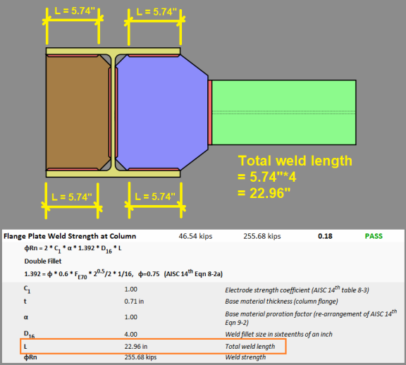
The weld between the flange plate and the column is considered to have no eccentricity.
The weld between the flange and the column is considered to have no eccentricity.
RISAConnection allows beam to column web moment connections for the Flange Plate and Direct Weld moment connections. When the beam frames into the column web, the total length of weld at each column inside flange (where the flange plate or transverse stiffener connects) is considered to resist the governing flange force.
The program assumes that only the welds at the column flange resist the flange force, not the weld at the column web. This methodology comes from the article Moment Connections to Column Webs by M. Thomas Ferrell in Modern Steel Construction.
For Extended End Plate moment connections the horizontal fillet distance of the beam (k1) is not counted for the 'inside' flange fillet welds, as it is impossible to weld in these locations.
If a fillet weld is specified between the beam web and the end plate, it is designed considering the recommendations of AISC Design Guide #4 (2nd Edition) Section 2.1.
This procedure uses an "effective" weld length that is calculated as: Leff = d/2 - kdet. The weld must also have a minimum size to develop the full tensile capacity of the beam web. This is checked in Weld Limitations.
Splice connections ignore all eccentricity from both shear and axial loads. When the ICR method is chosen the capacity is calculated using method outlined in section J2.4b of the AISC 360-10 specification. When the Elastic method is chosen the capacity is calculated using the method listed on page 8-12 of the AISC 14th Edition Manual.
Note:
Most eccentricities are ignored for Vertical Brace Connections as they are proportioned per the Uniform Force Method to eliminate all eccentricities.
Per AISC 360-10, Section J1.7, the effects of eccentricity are ignored on this connection.
For directly welded connections the axial (transverse) force is neglected on the fillet weld if it results in net compression. Per the AISC 14th Edition Manual, Page 13-11, the weld is designed for a peak stress of 1.25 times the average stress. In other words, a 0.80 reduction factor is applied to the strength. This factor is not given a variable in the code, so RISAConnection calls this β. If a double fillet weld is used, the two welds are taken into account in the C coefficient.
For clip angle connections the eccentricity between the axial (transverse) force and the CG of each C-shaped weld, which results in a prying effect, is considered. The eccentricity due to shear (longitudinal) force is ignored.
This connection is treated the same as a simple shear connection, with the exception of the altered Weld Geometry on the Double Clip Angle connection. For the Double Clip Angle connection the in-plane eccentricity effects on the weld to support are ignored, as it is assumed that the beam cannot shift vertically to allow the angles to rotate towards each other.
Per AISC Design Guide #24, Section 2.1., the 1.5 multiplier for transversely loaded welds is intentionally ignored in this case.
The eccentricity on through-plate connections is resolved through a force couple, such that no bending occurs on the weld segments. The weld on the "near" end of the connection takes the entire shear due to the beam reaction, as well as a component of the force couple due to eccentricity. The weld on the "far" end of the connection takes the other component of the force couple due to eccentricity. Any axial force in the connection is resisted by both "near" and "far" welds equally.
PJP (partial joint penetration) welds are sized using an "effective throat". The AISC Specification has requirements for minimum effective throat thicknesses listed in Table J2.3. The program compares the specified effective throat against the thicknesses of the materials, and lists the weld as 'failing' if it does not comply.
The filler metal matching as described for CJP welds is also checked, however an electrode strength that has less than the matching value is also acceptable, per Table 2.5 from the AISC Specification.
The strength reduction factor on PJP welds which are not loaded in pure shear or pure tension is interpolated as an effective factor as shown below:
Φeff = Φv + (Φt - Φv)(sin θ)1.5
Where:
Φv = Strength Reduction Factor for PJP Welds in Shear per AISC 360-10, Table J2.5
Φt = Strength Reduction Factor for PJP Welds in Tension or Compression per AISC 360-10, Table J2.5
θ = Angle between weld longitudinal axis and resultant load
For moment connections, the force on the weld is always normal to the weld axis, and is always in tension or compression. The strength of the weld is determined per Eqn J2-3 from the AISC Specification, using the appropriate values from Table J2.5.
For vertical brace connections the weld strength is compared against the resultant force regardless of whether the transverse force is a tension or compression. Since AISC 360-10 specifies different strength reduction factors (Φ, Ω) for longitudinal versus transverse loading, RISAConnection calculates an effective factor based on interpolation.
Per the AISC 14th Edition Manual, Page 13-11, the weld is designed for a peak stress of 1.25 times the average stress. In other words, a 0.80 reduction factor is applied to the strength.
CJP (complete joint penetration) welds are designed to develop the full strength of the base material. The metal used for the electrode must "match" the base material metal per the American Welding Society. The program compares the beam, column, and connector materials to the specified weld electrode to determine compatibility. If the materials are not compatible then the weld is considered 'failing'. The most stringent combination of base material/weld electrode is considered.
For an abbreviated list of matching metals, see the AISC Specification J2.6.
RISAConnection limits welds based on AISC limitations. A warning is provided if the welds violate these limitations.

Fillet welds are limited to a maximum size in order to maintain appropriate shelf dimensions. This is in the AISC specification section J2.2b. For a graphical representation of this requirement see the AISC 14th Edition Manual, figure 8-11. The maximum weld size is checked for the following welds:
Fillet welds are limited to a minimum size in order to prevent rapid cooling of the weld, which results in a loss in ductility. This is covered in the AISC Specification, Table J2.4. The limitation is based on the thickness of the thinner part joined. The minimum weld size is checked for all welds.
Fillet welds are limited to a minimum length of four times their nominal size. This is covered in the AISC Specification section J2.2b. The minimum weld length is checked for all welds.
Note:
Fillet welds are limited by RISAConnection to a maximum length of 100 times their leg dimension. The program is not currently configured to identify "end-loaded" welds, so this is a conservative limitation to avoid Eqn J2-1 from the AISC Specification. The maximum weld length is checked for all welds with a non-zero axial load.
Fillet welds may only be used for Extended End-Plate Moment Connections on beams which have flanges/beams not greater than 3/8" thick. For more information see AISC Design Guide #4 (2nd Edition), page 18.
This checks whether the weld will fit where it is attempting to be placed. This is a physical check. For example, if you are welding a 1/4" fillet (leg length) we will check to see if there is 1/4" of space on the member you are welding to. If the weld "falls" off the member you will fail this check.
Fillet welds must be sized to develop the full strength of the beam web in tension near the inside bolts for Extended End-Plate Moment Connections. For more information see AISC Design Guide #4 (2nd Edition), page 18.
See PJP Weld Strength.
See CJP Weld Strength.